
Podule access
|
|
Podule access |
|
A complete description is beyond the scope of this article. If you would like details (39 pages
of it, PostScript or DrawFiles), then you will find it at
the
Acorn ftp site mirror ![]() .
.
Oddly, the Acorn ftp site at RISC OS Ltd doesn't appear to have these files.
  Address:  %000000110aabbcccaaaaaaaaaddddd00

  Where:  aa..aa is the device address in the memory map

          bb     is the access type:
                    %00 slow
                    %01 medium
                    %10 fast
                    %11 synchronous

          ccc    is the bank:
                    0 - IOC control registers
                    1 - Floppy disc controller (fast)
                    2 - Econet (sync)
                    3 - Serial port (sync)
                    4 - Expansion cards (slow/med/fast/sync)
                    5 - Harddisc (med)
                    5 - Printer (fast)
                    7 - Expansion cards (slow)

          ddd    is an offset in the device

Thus, basically, the I/O memory map looks like:
    &3310000    Floppy disc controller
    &33A0000    Econet ADLC
    &33B0000    Serial port controller
    &3240000    Internal expansion cards (slow)
    &32C0000    Internal expansion cards (medium)
    &3340000    Internal expansion cards (fast)
    &33C0000    Internal expansion cards (sync)
    &32D0000    Harddisc interface
    &3350010    Printer Data
    &3270000    External expansion cards (slow)

    THIS IS FOR THE ARCHIMEDES; THINGS ARE DIFFERENT ON THE RISCPC
>SYS "Parallel_HardwareAddress" TO addr%
>P. ~addr%
   30109E0
>P. !addr%

Internal error: abort on data transfer at &022B1254
>
As BASIC runs in USR mode, it fails.
   10 DIM code% 128
   20 P% = code%
   30 [ OPT 2
   40   SWI     "Parallel_HardwareAddress"  ; address is in R0
   50   SWI     "OS_EnterOS"                ; go to SVC mode to access hardware!
   60   MOV     R2, #&FE
   70   STRB    R2, [R0, #0]  ; write &FE to parallel port data register
   80   LDRB    R0, [R0, #0]  ; load R0 with word pointed to by R0
   90   TEQP    PC, #0
  100   MOV     R0, R0
  110   MOV     PC, R14
  120 ]
  130 PRINT ~USR(code%)
The result of this is
FE.
You can, from RISC OS, use:
SYS "Parallel_Op", 0 TO ,, status%
to read the value of the status bits.
With my printer (HP DeskJet 500, CC's TurboDriver cable), the results are:
The same thing may be performed with direct hardware access:
   10 DIM code% 128
   20 P% = code%
   30 [ OPT 2
   40   SWI     "Parallel_HardwareAddress"
   50   SWI     "OS_EnterOS"
   80   LDRB    R0, [R0, #4]
   90   TEQP    PC, #0
  100   MOV     R0, R0
  110   MOV     PC, R14
  120 ]
  130 PRINT USR(code%)
Once you have the address of the parallel port cached, you don't need to look it up again. So you can reduce the call to the basics. Indeed, if you include this in SVC code (ie, some form of device driver) you could reduce the call to just an LDRB (if the address is preloaded into a register), instead of calling OS_ParallelOp each time around.
Obviously, such hardware poking is frowned upon, but it is sometimes necessary in the quest for maximum speed. D'you think any of the iomega Zip drivers use OS_ParallelOp? :-)
This will only work for devices using an ISA mapping. This means the A5000 (82C710), and the
RiscPC/A7000 (37C665 see below). I would imagine the RiscStation and Mico, and (when it finally
turns up) the Omega would also all use off-the-shelf ISA combo chips instead of discrete
hardware.
What this does mean, however, is the software that does this may fail on the early
machines like the A310 and the A3000. I don't have one running to check this. Caveat emptor.
For what it is worth, here are the addresses from the 37C665 datasheet:
  DATA port        Base address + &00     LDRB Rx, [Rx, #0]
  STATUS port      Base address + &01     LDRB Rx, [Rx, #4]
  CONTROL port     Base address + &02     LDRB Rx, [Rx, #8]
  EPP ADDR port    Base address + &03     LDRB Rx, [Rx, #12]
  EPP DATA port 0  Base address + &04     LDRB Rx, [Rx, #16]
  EPP DATA port 1  Base address + &05     LDRB Rx, [Rx, #20]
  EPP DATA port 2  Base address + &06     LDRB Rx, [Rx, #24]
  EPP DATA port 3  Base address + &07     LDRB Rx, [Rx, #28]
Remember, the bottom two bits are zero, so all addresses are shifted. The LDRB shows this.
  PORT       D0      D1      D2      D3      D4      D5      D6      D7

  DATA          ....bits 0-7 of the data to be sent to the printer....

  STATUS     TMOUT   -       -       |ERR    SLCT    PE      |ACK    |BUSY

  CONTROL    STROBE  AUTOFD  |INIT   SLC     IRQE    PCD     -       -

  ERR ADDR   PD0     PD1     PD2     PD3     PD5     PD5     PD6     AD7

  EPP DATA             ...PD0 to PD7 for all EPP DATA ports...
SYS "Podule_ReturnNumber" TO podcnt%
FOR podule% = 0 TO (podcnt%-1)
  SYS "XPodule_HardwareAddresses",,,, podule% TO baseaddress% ; err%
  IF (err% AND 1) THEN
    PRINT "Podule "+STR$(podule%)+" is empty"
  ELSE
    PRINT "Podule "+STR$(podule%)+" base &"+STR$~(baseaddress%)
  ENDIF
NEXT
The program above returns the address used for synchronous access. The podule identity stuff is
always accessed synchronous.
You can find out more about podules at the above link, or you can download the older
A-series podule
information ![]() (more out of date, but it is in text format).
(more out of date, but it is in text format).
You might also enjoy a perusal of Theo Markettos' web
site ![]() .
.
REM >visioncode

ON ERROR PRINT REPORT$+" at "+STR$(ERL/10) : END

PROCassemble
visionbase% = 0

SYS "Podule_ReturnNumber" TO podcnt%
FOR podule% = 0 TO (podcnt%-1)
  SYS "XPodule_HardwareAddresses",,,, podule% TO baseaddress% ; err%
  IF (err% AND 1) THEN
    PRINT "Podule "+STR$(podule%)+" not installed"
  ELSE
    PRINT "Podule "+STR$(podule%)+" base &"+STR$~(baseaddress%);
    B% = baseaddress%
    IF USR(find_podule%) = 1 THEN
      visionbase% = baseaddress%
      PRINT "...this is a Vision."
    ELSE
      PRINT
    ENDIF
  ENDIF
NEXT

REM Once we know our base address, we can set up some offsets.
REM The down conversion changes our podule access methods.
visionheader% = visionbase% - &180000 : REM Base, slow access
visionctrl% = visionheader% + &102800 : REM Control, fast access
visiondata% = visionheader% + &103800 : REM Data, fast access
visionstat% = visionheader% + &100080 : REM Status, fast access
visionrst%  = visionheader% + &2000   : REM Reset, slow access

REM Code to reset, check, and fetch image removed
REM not necessary for this example

END

DEFPROCassemble
  DIM code% 76
  FOR loop% = 0 TO 2 STEP 2
    P% = code%
    [ OPT     loop%

      \ On entry, R1 = base address
      \ On exit,  R2 = 1 if Vision, else 0
    .find_podule%
      ; Stash R14 and enter SVC mode.
      STMFD   R13!, {R14}
      SWI     "OS_EnterOS"

      ; Set flag to TRUE. If a test fails, flag will be FALSified. <g>
      MOV     R0, #1

      ; Is +12 &AF?
      LDRB    R2, [R1, #12]
      CMP     R2, #&AF
      MOVNE   R0, #0

      ; Is +16 &00?
      LDRB    R2, [R1, #16]
      CMP     R2, #&00
      MOVNE   R0, #0

      ; Is +20 &2D?
      LDRB    R2, [R1, #20]
      CMP     R2, #&2D
      MOVNE   R0, #0

      ; Is +24 &00?
      LDRB    R2, [R1, #24]
      CMP     R2, #&00
      MOVNE   R0, #0

      TEQP    PC, #0
      MOV     R0, R0

      LDMFD   R13!, {PC}
    ]
  NEXT
ENDPROC
For an interesting look at the Vision digitiser in use, you can either see the Willow (Alyson
Hannigan) area of my website at
http://www.heyrick.co.uk/willow/
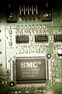 The name may not make much sense to you, but if you are using a RiscPC then it is a very
important name. The 37C665 (pictured) is the device that handles your parallel port, serial port,
floppy disc, IDE bus...
The name may not make much sense to you, but if you are using a RiscPC then it is a very
important name. The 37C665 (pictured) is the device that handles your parallel port, serial port,
floppy disc, IDE bus...In order to read the configuration of the 37C665, we need to write &55 (85) to port &3F0. However, we don't yet know where in memory the device is located. There are two ways to determine the location of the device:
&30109E0.&278 << 2
which is &9E0.
So, port &3F0 (which becomes &FC0 when shifted) is where we write &55 to set the
device into configuration mode. Two consecutive writes must be made, so it is worth switching
off interrupts.
This will only work on the RiscPC, and you MUST release yourself from configuration
mode before attempting to use your computer. It goes without saying that you ONLY read the
configuration registers, never write to them!
Once we are in configuration mode, we write a register number (0-15) to &3F0 and we can then read the value of that register from &3F1. It is simple to whizz through the registers, dumping the contents to memory as we go.
To leave configuration mode, we write &AA to &3F0. This must be done or your computer's I/O will just cease to function.
This code will ONLY work on the 37C665 fitted into the RiscPC. It is worth noting that the 37C666 (basically a 665 but uses hardware links to configure it, the sort of thing you'd find on a cheap ISA combo-card) uses the magic value &66 to enter configuration mode. If your machine has a different I/O chip, like the RiscStation or A7000, you might like to try a different machine value if &55 doesn't work. Maybe &99? This is speculation though, as my data sheet doesn't cover the 37C669. Please email me if you discover a sequence that works.
November 2001:
A friend has got a Bush Internet box for me, Toy-R-Us are apparently selling them for TWENTY
POUNDS!!! Anyway, when I've paid him and taken delivery of it, I'll play around, see what is
inside it. If you have a Bush internet box, then you might like to know that it should be
possible to boot the thing into the command line (or BASIC?) by holding down the Shift key while
booting.
This takes place in SVC mode, with interrupts disabled. The code is pretty basic really. I rather
suspect that the final TEQP could be combined into the MOVS PC, R14 to
restore the flags and interrupt state. But doing it this way makes sure... The code is not
32bit compliant.
ON ERROR PRINT REPORT$+" at line "+STR$(ERL/10) : END

DIM code% 128

FOR l% = 0 TO 2 STEP 2
  P% = code%
  [ OPT     l%

    STR     R14, [R13, #-4]!

    SWI     "OS_EnterOS"
    TEQP    PC, #&0C000003     ; interrupts disabled

    LDR     R0, base_address
    MOV     R1, #&55
    STRB    R1, [R0, #&FC0]    ; port &3F0
    STRB    R1, [R0, #&FC0]
    ; Now in 37C665 software configuration mode

    ADR     R2, registers      ; Where to store registers
    MOV     R3, #0             ; Register number (& offset)

  .read_loop
    ; Write desired register number to address &3F0
    STRB    R3, [R0, #&FC0]
    ; Now read register contents from address &3F1
    LDRB    R1, [R0, #&FC4]
    ; Store it in our register block
    STRB    R1, [R2, R3]

    ADD     R3, R3, #1
    CMP     R3, #16
    BLT     read_loop

    MOV     R1, #&AA
    STRB    R1, [R0, #&FC0]
    ; Now out of software configuration mode

    TEQP    PC, #&08000000     ; interrupts enabled, USR mode
    MOV     R0, R0

    LDR     R14, [R13], #4
    MOVS    PC, R14


  .base_address
    EQUD    &03010000

  .registers
    EQUD    0
    EQUD    0
    EQUD    0
    EQUD    0
  ]
NEXT

PRINT "Examining multi-I/O chip configuration...";
CALL code%
PRINT "done."''

PRINT "Device identification ";
CASE registers?13 OF
  WHEN &65 : PRINT "FDC37C665GT";
  WHEN &66 : PRINT "FDC37C666GT"; : REM Different magic value, so should not happen!
OTHERWISE  : PRINT "Error! Device ID "+STR$~(registers?13)+" unrecognised!" : END
ENDCASE
PRINT ", revision "+STR$(registers?14)

END
Briefly, the registers are: