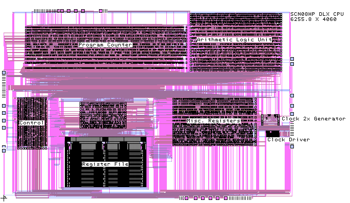
The 'PC' block includes the branch/jump target address calculation via a 32-bit CLA adder; this block also includes the instruction memory interface. The 'misc registers' block includes the data memory interface. The 'control' block includes the logic for all of the pipeline stages. The 'Register' file is a 32-bit dual port register file. The ALU includes a 32-bit CLA adder/subtractor and barrel shifter. All blocks are implemented using the MSU SCMOS standard cell library except for the register file. All blocks except for the dual port register file were synthesized via Synopsys.
Mentor AutoCells was used for place and route of the Standard Cell blocks; Mentor Memory Builder was used for the register file; Mentor MicroRoute was used to route the macro blocks. The macro block routing uses 3 layer routing and currently takes 20 minutes on a SUN 140Mhz UltraSparc. In fairness, it should be noted that routing time for the top-level blocks can vary widely depending upon the final floorplan and block terminal placement.
This design has not been fabricated; it is being used to drive our tool methodology and library design efforts. It has been tested via an LSIM switch level simulation performed on a mask-level extracted transistor netlist.