![]()
here.
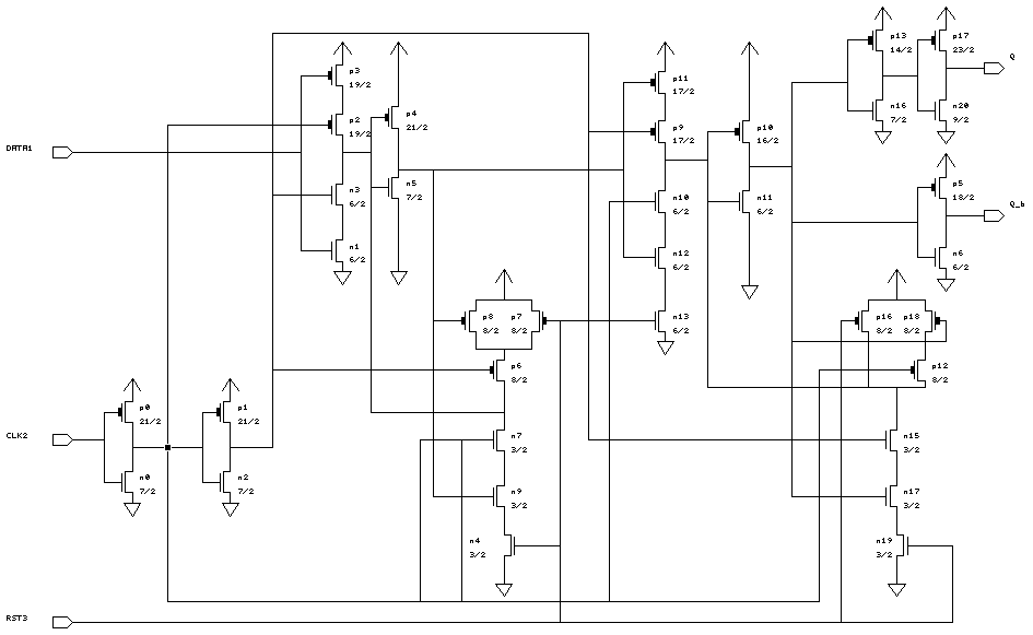
Q_b = Qn'
------------------------------------------
CLK	DATA	RST	Q	Q_b
------------------------------------------
l2h	x	1	Qn-1	Qn-1'
h2l	x	1	DATA	DATA'
x	x	0	0	1
------------------------------------------
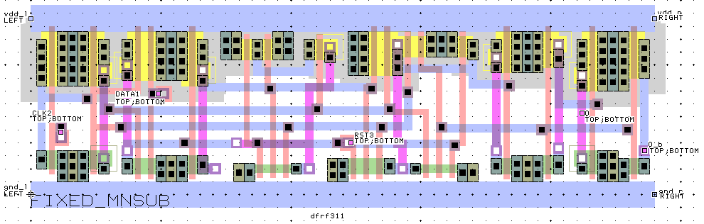
--------------------------------------------
Name	X_loc	Y_loc	   Capacitance (fF)
	lambda  lambda   2U	1.2U	0.8U
--------------------------------------------
CLK2	11.5	24	62.8	28.9	18.9
DATA1	49	39	58.6	28.8	18.5
Q	212	31.5	-	-	-
Q_b	236	17	-	-	-
RST3	123	20	89.5	38.8	22.9
--------------------------------------------