 Microsystems Prototyping Laboratory
 Microsystems Prototyping Laboratory
![]()

here.
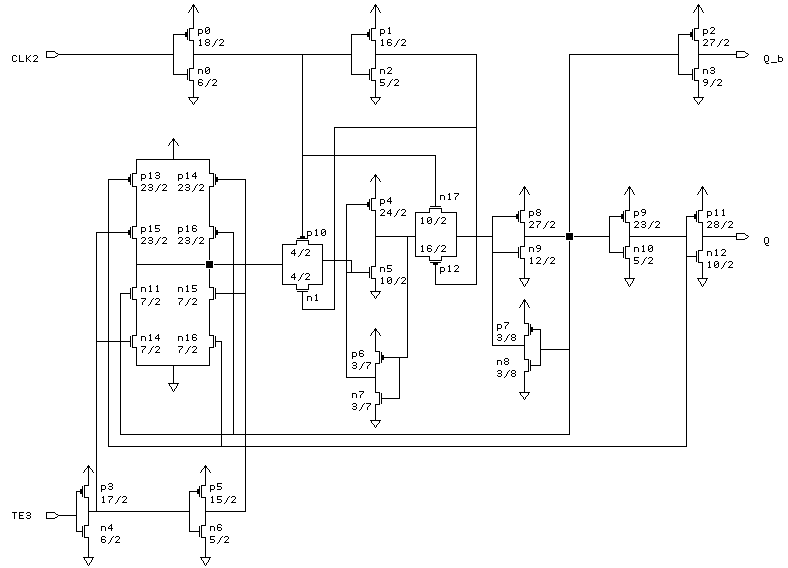
Q_b = Qn'
------------------------------
CLK	TE	Q	Q_b
------------------------------
l2h	0	Qn-1	Qn-1'
h2l	0	Qn-1'	Qn-1
x	1	Qn-1	Qn-1'
------------------------------
--------------------------------------------
Name	X_loc	Y_loc	   Capacitance (fF)
	lambda  lambda   2U	1.2U	0.8U
--------------------------------------------
CLK2	223	16	58.0	27.0	17.3
Q	16	24	-	-	-
Q_b	61	20	-	-	-
TE3	130	18	56.5	27.8	17.4
--------------------------------------------