![]()
Copyright © 1998 University of Manchester
|
|
4.4.3 LPM_SHIFTREG |
|
Copyright © 1998 University of Manchester |
Universal Shift Register

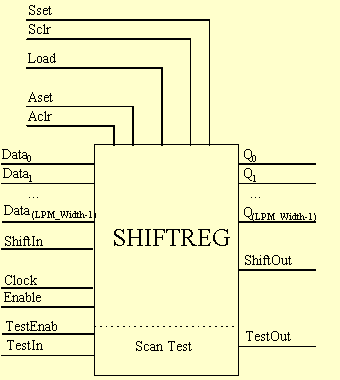
| Description | Comments | |||
| Data for parallel load of shift register | Vector, LPM_Width wide | |||
| Clock, positive edge triggered | ||||
| Clock enable input | Default is enabled (High) | |||
| Input for serial data during shift | ||||
| High (1): Load operation
Low (0): Shift operation | Default is low (0) - shift operation. Note 2. | |||
| Output for parallel data | Vector, LPM_Width wide | |||
| Output for serial data during shift | ||||
| Set register value to all 1's or to the value of LPM_Avalue, if present. | Note 4, Note 5 | |||
| Clear the register (set to all 0's) | Note 5 | |||
| Set register value to all 1's or to the value of LPM_Svalue, if present | Note 4, Note 5 | |||
| Clear the register (set to all 0's) | Note 5 | |||
| Test clock enable input | ||||
| Serial test data input | ||||
| Serial test data output | TestOut = QLPM_Width-1 |
Note 1: At least one of Data, Aset, Aclr, Sset, Sclr and/or ShiftIn must be used.
Note 2: Synchronous parallel load. For parallel load operation Load must be high (1) and Enable (the clock enable) must be High or unconnected.
Note 3: Either ShiftOut or Q or both must be used.
Note 4: Sset and Aset will set the count to the value of LPM_Svalue or LPM_Avalue respectively, if those values are present. If no LPM_Svalue is specified, then Sset will set the count to all ones, likewise Aset.
Note 5: Sset, Sclr, Aset and Aclr affect the output (Qi ) values before the application of polarity to the ports.
Note 6: Either all of the Test ports must be connected or none of them.
| Value | Comments | ||
| LPM Value > 0 | Width of input and output vectors | ||
| LPM Value | Value loaded by Aset | ||
| LPM Value | Value loaded by Sset | ||
| LPM Value | Value loaded at power-on | ||
| LEFT|RIGHT | Default is LEFT. Note 1. |
Note 1: A left shift implies that the data is being shifted into the LSB and out the MSB. The LSB gets the value on the ShiftIn port. The ShiftOut port is always equal to QLPM_Width-1.
|
|
| Output | |||
| Asynchronous value.
Note 1 | ||||||
| Synchronous value
Note 2 | ||||||
| No change (clock not enabled) | ||||||
| No change (clock not enabled) | ||||||
| Parallel load Register from Data | ||||||
| Qi is shifted into Qi+1
ShiftIn is loaded into Q0 | ||||||
| Qi is shifted into Qi+1
TestIn is loaded into Q0 |
Note 1: The asynchronous value is determined by which asynchronous port is high: Aclr or Aset. If Aclr and Aset are both high, then the output is UNDEFINED. Asynchronous controls have priority over synchronous controls. If the LPM_Avalue property is defined, then the Aset port, when active, will set the FFs to the value of the LPM_Avalue.
Note 2: The synchronous value is determined by which synchronous port is high: Sclr or Sset. If more then one synchronous port is high, then Sclr takes priority over Sset. Asynchronous controls have priority over synchronous controls. If the LPM_Svalue property is defined, then the Sset port, when active, will set the Q to the value of the LPM_Svalue.
|
Copyright © 1998 University of Manchester |