Introduction
This simulation looks at the SPARC MBUS interface and tests the
student's ability to create a VHDL model that duplicates observed
functional behavior. In other words, it tests MODELING ability rather
than mastery of syntactical language elements.
To Do
Unpack the file sim2.zip in the directory above
which your 'vhdl_course' directory is located. The archive contents are:
./vhdl_course/src/sim2 --- VHDL source code for elements of the sim2 library
./vhdl_course/src/Makefile/Makefile.sim2 --- makefile for the sim2 library
./vhdl_course/src/sim2.do -- wave command file
./vhdl_course/src/cpu0_f11-18.dat -- data file
./vhdl_course/src/cpu1_f11-18.dat -- data file
./vhdl_course/src/cpu0_f11-19.dat -- data file
./vhdl_course/src/cpu1_f11-19.dat -- data file
./vhdl_course/src/cpu0_f11-20.dat -- data file
./vhdl_course/src/cpu1_f11-20.dat -- data file
./vhdl_course/src/cpu0_f11-21.dat -- data file
./vhdl_course/src/cpu1_f11-21.dat -- data file
./vhdl_course/src/cpu0_f11-22.dat -- data file
./vhdl_course/src/cpu1_f11-22.dat -- data file
./vhdl_course/obj/qhdl/sim2/.... -- object directory
./vhdl_course/obj/qhdl/sim2/ts/.... -- timestamp directory
After unpacking the file, you will need to do the following:
% cd vhdl_course/src
% qhmap sim2 ../obj/qhdl/sim2
% make -f Makefiles/Makefile.sim2 TOOLSET=qhdl
This will modify your local 'modelsim.ini' file so that it knows the
directory mapping for the 'sim2' library and compile the 'sim2' library.
MBUS Operation
The components in the 'sim2' library model the MBUS access protocol as
discussed in class. The important entities/configurations are as follows:
- 'cpu' -- an entity used emulate a CPU's MBUS accesses. The CPU model
reads a datafile specified by the 'infile' generic that determines how
long the cpu component is to retain the bus, the address to place on
the address bus during the MBUS access, and when the next request
should take place. The 'cpu_behv.vhd' contains the architecture for
the CPU; currently this architecture is empty and it is your job to
supply the needed code. There will be more discussion on the CPU
entity later in this document.
- 'arbiter' -- an arbiter entity that implements a round robin
priority scheme. This version of the arbiter is currently limited to
only four pairs of bus request/bus grant lines.
- 'tb' -- an entity testbench that connects two CPU components to
an arbiter component.
- 'stim' -- a stimulus entity that provides the clock signal for
the simulation.
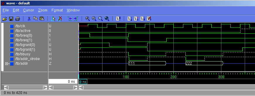
- 'cfg_tb_f11_18' -- configuration whose simulation should produce
a waveform equivalent to Figure 11-18 of the HyperSparc User's guide.
Associated CPU data files are cpu0_f11-18.dat, cpu1_f11-18.dat. The
simulation waveform is shown below:
- 'cfg_tb_f11_19' -- configuration whose simulation should produce
a waveform equivalent to Figure 11-19 of the HyperSparc User's guide.
Associated CPU data files are cpu0_f11-19.dat, cpu1_f11-19.dat. The
simulation waveform is shown below:
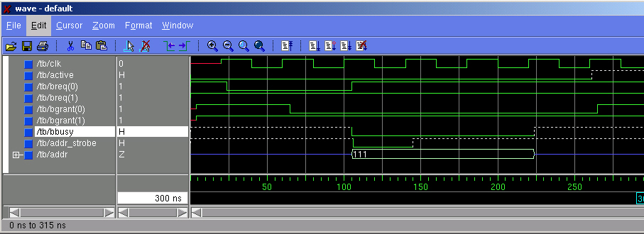
- 'cfg_tb_f11_20' -- configuration whose simulation should produce
a waveform equivalent to Figure 11-20 of the HyperSparc User's guide.
Associated CPU data files are cpu0_f11-20.dat, cpu1_f11-20.dat. The
simulation waveform is shown below:
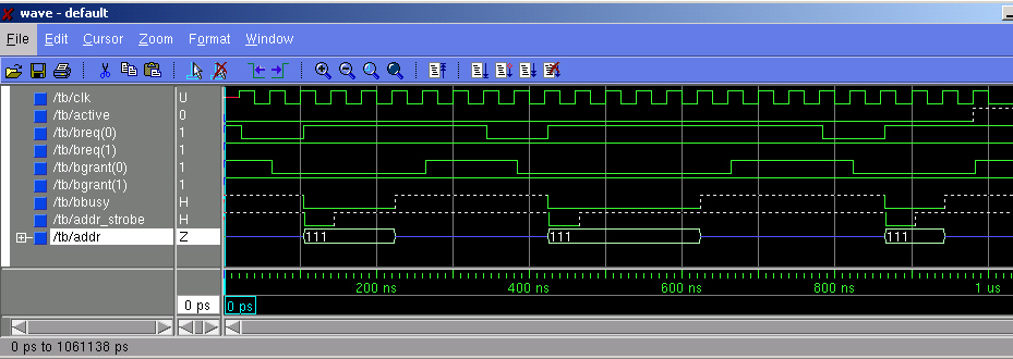
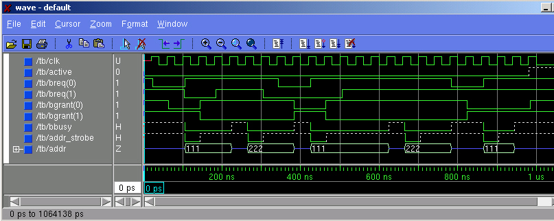
- 'cfg_tb_f11_21' -- this configuration exercises
a more complex request sequence than previous files (in this simulation,
one CPU makes 3 requests, and the other CPU does not make a request)
Associated CPU data files are cpu0_f11-21.dat, cpu1_f11-21.dat. The
simulation waveform is shown below:
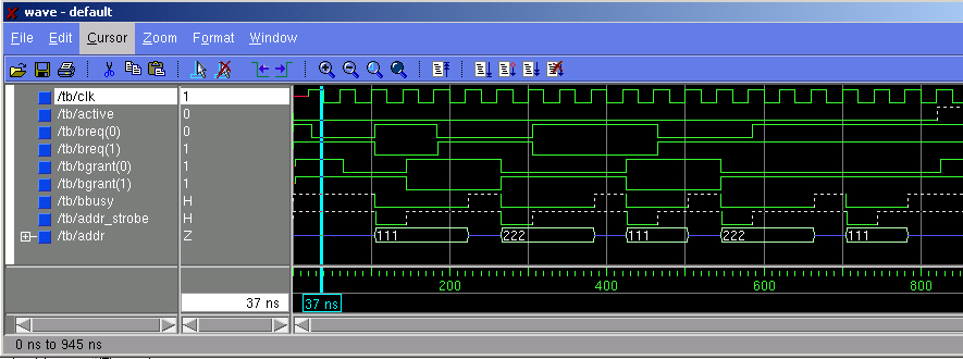
- 'cfg_tb_f11_22' -- this configuration combines previous
data files to make a complex request sequence.
Associated CPU data files are cpu0_f11-22.dat, cpu1_f11-22.dat. The
simulation waveform is shown below:
What You Must Do
You are to complete the 'cpu_behv.vhd' code such that this architecture
can be used to exercise the arbiter model capability. In order to do this we must have
a controlled method by which a CPU can generate bus requests. This will be
accomplished by having the CPU model architecture read a data file that determines when
it will make a bus request, and for how long it will 'hold' the bus.
The definition of the data file format is:
- The first line contains an integer which defines the clock cycle
in which the FIRST mbus request is made (a value of '1' indicates the
MBUS request should be made in first clock cycle). A value of -1 means that no request
is to be made (any subsequent lines can be ignored).
- Each line after the first contains three numbers. The first
number specifies how many clock cycles the processor is hold the bus
after it has been granted the bus (how many clock cycles the 'bbusy'
line to be held low). The third number specifies the address to be
placed on the address bus during assertion of the 'bbusy' line.
The second number specifies how many clock
cycles from the CPU's assertion of 'bbusy' to the next assertion of
its bus request line. If you look at the reference waveform for
'cfg_tb_f11_20' and the associated data files, you can see how this
works. If the second number is a '-1', then this means that no
further requests are to be made.
The waveforms shown above illustrate correct execution of the CPU architecture for the
associated data files. Note the arbiter model is RESPONDING to CPU requests. You do not have
to modify the arbiter model - it is already provided. The CPU architecture (cpu_behv.vhd) file
that is given in the zip archive is empty - you will have complete it to provide the needed
capablity. The provided VHDL configurations simply test different situations by specifying different
input files to the CPU.
The timing produced by your CPU architecture model
must be 'clock phase accurate'; this means that the signals must transistion in the
same clock phases as they do in the reference wave forms but the signals
DO NOT have to transistion at exactly the same time as the reference
waveforms (in these simulations, all signals transition after the
rising clock edge and are stable before the falling clock edge and your model should do the same).
The port definition of the CPU entity is as follows:
- clk, input clock
- breq, output, connected to 'breq' input of arbiter.
- bgrant, input, connected to 'bgrant' output of arbiter.
- bbusy, output, modeled as an 'open drain' driver. The CPU
component can only
drive this line with a '0' or 'Z' value; this line is shared by other
CPU components in the system and has a pullup on it.
- addr_strobe,output, modeled as an 'open drain' driver. The CPU
component can only
drive this line with a '0' or 'Z' value; this line is shared by other
CPU components in the system and has a pullup on it.
- addr, output, modeled as a tri-state driver. This is the common address bus for all CPU
components. When the CPU does not have ownership of the bus it should
drive this output with a 'Z' value.
- active, output, modeled as an 'open drain' driver. The CPU
component can only
drive this line with a '0' or 'Z' value; this line is shared by other
CPU components in the system and has a pullup on it.
The 'active' output is not part of the MBUS interface. It is a shared
line monitored by the 'stim' entity. The default output value of the
'active' output should be a '0'; the CPU component should drive
the 'active' output with a 'Z' after it has finished with its last
transaction (released 'bbusy' and detected that it needs to generate
no more bus requests). As long as any CPU is generating bus requests,
the 'active' line will be a '0'. When all CPU components have
finished generating requests, the 'active' line will be pulled to a
'H'; this will be detected by the 'stim' component and the 'stim'
component will stop generating clock pulses.
To Turn In
The only file I am interested in is 'cpu_behv.vhd'.
From the
directory above 'sim2', copy the script
submit_sim2.pl .
Then execute the script via "perl submit_sim1.pl"
This will create a compressed tar file
of your 'sim2' directory and will mail it to me.