Using Xilinx Foundation
Series Software:
Function Simulation
In the Waveform Viewer

- In the Project Manager window
select SIM Funct (Functional Simulation). The empty Logic Simulator and Waveform Viewer
windows should now be open. Note:
The schematic has to be completed before this step. See Using
Xilinx Foundation Series Software: Schematic Entry.
- Signals must be added to the Waveform Viewer so they can be simulated. In the Signal menu, select Add Signals.
All the signals and probes will be presented in this window. Select the
important signals to view by holding down Ctrl
and then Clicking on each signal that you wish to add, then Click
Add. Click on Close. The
Waveform Viewer window should now list the signals you chose.

- You must now apply stimulus to the input
signals. In the Signal menu, select Add Stimulators.
The Stimulator
Selection window will now appear
with a keyboard, clocks, and counters. We will use the counter
because it will go through every possible input value automatically. The
counter is labeled Bc (Binary Counter). To assign the 0 bit (B0) of
the counter to the first input in your design, you should select the signal
in the Waveform
Viewer by clicking on it, it
will be highlighted. Then click on the 0 bit in the counter and the signal
will now be assigned to that (B0) value of the Bc for
the duration of the simulation. B0 should appear in the column next to
the signal name in the Waveform Viewer window. Assign each input signal to a different bit in the Bc. Click
Close. Note:
DO NOT apply stimulus to the Outputs.

- The speed of the Bc must
be changed before simulation. In the Options menu,
select Preferences. In the Clocks section
of the Preferences window change the B0 clock frequency
to 50MHz. Click OK.

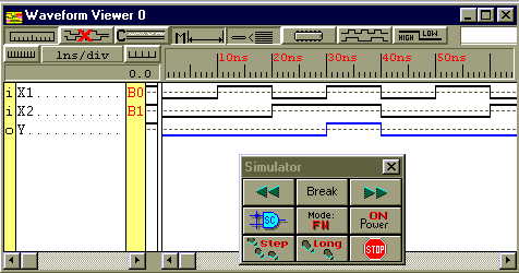
- You are now ready to simulate your design.
In the small Simulator window select Step
 .
Waveforms should now appear that correspond to each signal that is being
viewed. Black waveforms are for inputs, blue waveforms
are for outputs.

- Step the simulation forward a couple of steps and
observe the waveforms.

See Using
Xilinx Foundation Series Software: Functional Simulation in the Schematic
Editor.
Download a Text only printable version of these instructions (Word 95 7.0):
WaveformSimulate.doc
Back to the Xilinx Foundation
Series Main Menu