Descriptions mixtes analogiques-numériques

(PLL circuit - principe, PLL - le schéma, PLL - composants, comparateur analogique, détécteur de phase & sa structure, filtre analogique, PLL - l'architecture)
 
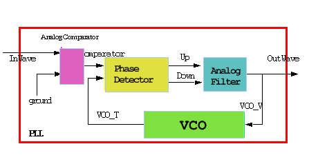
PLL - circuit à boucle de phase et son architecture en VHDL-AMS:
Le circuit PLL est bon exemple d'un système mixte analogique-numérique. Notre modèle exploite plusieurs mécanismes VHDL-AMS prévus pour la modèlisation mixte dont:

PLL - le schéma:
 Clickable Image CommentCommentCommentComment


PLL - les composants:
 
VCO -  description comportementale-analogique:
 
entity VCO is
generic( 
fc: real := 1E6; -- cut-off frequency fc for the tension Vc 
df: real := 0.5E6; -- [Hz/V], rapport frequency/tension 
Vc: voltage := 0.0 -- tension for central frequency );
port 
     quantity Vin: in voltage;  
     terminal OutTerminal:  electrical);
end VCO; 
 
 
architecture PhaseIntegrator of VCO is
constant TwoPi: real := 6.283118530718; -- 2pi
quantity Phase : real; -- phase is a free quantity:
quantity Vout across Iout through OutTerminal to ground;
begin
break Phase => 0.0;
-- break allows to define the initial conditions
break Phase => Phase mod TwoPi on Phase'above(TwoPi);
-- break allows to keep the phase interval between 0 and 2pi
Phase'dot == TwoPi*realmax(0.5E6, fc+(Vin-Vc)*df); 
-- phase statement
Vout == 2.5*(1.0+sin(Phase));  
-- output statement
end PhaseIntegrator; 
 

Comparateur analogique - description comportementale - analogique:
 
entity AnalogComparator is
  generic( Vthreshold: voltage := 0.0 ); -- [V] threshold tension
  port(terminal Pve_T,Nve_T: electrical; -- analog entry
       signal Out_T: out BIT ); -- digital output
end AnalogComparator; 
 
 
architecture Behavior of AnalogComparator is
quantity DeltaV across Pve_T to Nve_Y; -- tension at differential entry
begin
-- the architecture consists of one concurrent signal assignment statement
Vout <= `1' when DeltaV'above(0.0)
-- trigger event when V+>V-
   else `0' when not DeltaV'above(0.0);
-- trigger event when V+<=Vt-
end Behavior; 
 

Comparateur de phase - description structurelle - logique:
 
 
entity RSFF is
  generic (DelayQ, DelayQB: TIME := 0 ps);
  port ( SB,RB: in bit; Q,QB: out bit);
end  RSFF;
 
 
architecture Behavior of RSFF is
begin
-- set Q as a NAND operation
   Q <= SB nand QB after DelayQ;
-- set QB as a symmetrical NAND operation
   QB <= RB nand Q after DelayQB;
end Behavior; -- RSFF


entity PhaseDetector is
port( In1,In2 : in bit; Up,Down: out bit);
end PhaseDetector; 
 
architecture Structural of PhaseDetector is
signal UpB,DownB,TQ,SUp,RDown,BQB,M : bit; -- internal signals
component RSFF is -- components used in the architecture
  port( SB,RB: in bit; Q,QB: out bit);
end component;
begin 
-- logic operations
  SUp <= M and TQ;
  RDown <= M and BQB;
  M <= not( TQ and UpB and DownB and BQB);
-- instantiation of RS flip-flops
  RST: RSFF port map( SB=>UpB, RB=>M, Q=>TQ, QB=>open );
  RSB: RSFF port map( SB=>M, RB=>DownB, Q=>open, QB=>BQB );
  RSUp: RSFF port map( SB=>SUp, RB=>M, Q=>Up, QB=>UpB );
  RSDown: RSFF port map( SB=>M,RB=>RDown,Q=>DownB,QB=>Down );
end Structural; -- PhaseDetector
 

Filtre analogique - description structurelle - analogique:
 
entity AnalogFilter is
generic (InCurrent : current := 100E-6; -- [A] input current
-- generic values for components
         R1: REAL := 100E3; R2: REAL := 10E3;
         C1: REAL := 100E-12; C2: REAL := 3.3E-9 );
port (signal Up,Down : bit;
-- the signals controlling charge-pump phase comparator
      terminal Filter_T: electrical -- analog output pin );
end AnalogFilter;
  
architecture Circuit of AnalogFilter is
terminal Vc1_T,Vc2_T :electrical; -- internal node
quantity Isource through Vc1_T to ground; -- courrent source
begin
-- equations modeling the behavior of current sources
if Up = `1' and Down = `0' use  
  Isource == 100E-6; -- 100mA
elsif Up = `0' and Down = `1' use  
  Isource == -100E-6; -- -100ma
else Isource == 0.0; -- no current;
-- instantiation of filter components
C1: capacitor generic map (100E-12) port map(Vc1_T,ground);
R1: resistor generic map (100E3) port map(Vc1_T,Vfilter);
R2: resistor generic map (10E3) port map(Filter_T,Vc2_T);
C2: capacitor generic map (3.3E-9) port map(Vc2_T,ground);
end Circuit; 
 

Description de la PLL - assemblage des composants prédéfinis ci-dessus - description structurelle - mixte:
 
entity PLL is
  port(terminal InWave_T,OutWave_T: electrical);
end PLL; 
 
architecture MixedSignal of PLL is
signal Vcomparator,Up,Down,Vcounter,VCO_D : bit;  
-- internal signals
terminal Filter_T,VCO_T : electrical;  
-- internal terminals
quantity Filter_V across FilterT to ground 
-- tension at filter output
quantity VCO_V across VCO_T to ground 
-- tension at VCO output
component AnalogComparator is
  port(terminal Pve_T,Nve_T: electrical; -- analog inputs
       signal Vout : out bit ); -- digital output
end component;
component PhaseDetector is
  port( In1,In2 : in bit; Up,Down : out bit );
end component;
component AnalogFilter is
  port (signal Up,Down: bit; -- digital inputs
        terminal Filter_T: electrical ); -- analog output
end component;
component VCO is
  port(quantity Vin: in voltage;terminal Out_T : electrical);
end component;
begin
Comparator_L: AnalogComparator  
  port map (Pve_T => InWave_T, Nve_T => ground 
             Vout => Vcomparator );
PhaseDetector_L: PhaseDetector  
  port map ( In1 => Vcomparator, In2 => VCO_T, Up => Up,  
             Down => Down);
Filter_L: AnalogFilter  
  port map (Up => Up, Down => Down, Filter_T => VCO_V );
VCO_L: VCO  
  port map ( Vin => VCO_V, Out_T => VCO_T );
-- analog to digital conversion of VCO output
VCO_D <= `0' when VCO_V'above(2.5) -- logic threshold 2.5V
    else `1' when not VCO_V'above(2.5);
end MixedSignal; -- PLL