|
Part 2 Technical Topics : Future of Verilog
Connecting
other scripting languages to Verilog VCD (Value
Change Data)
Verilog-2000 The final draft of Verilog-2000 is completed on March 1st 2000. Once IEEE approval is done it will be a new Verilog HDL standard called IEEE Std. 1364-2000. This new standard contains 30 new enhancements over earlier standard for higher level, abstract syatem level modeling. It adds powerful capabilities Intellectual Property modeling, greater deep submicron accuracy and scalable, re-usable modeling. Analog Verilog
The intent of the Verilog-AMS standard is to define extensions to the Verilog standard (OVI 2.0 / IEEE 1364) for describing analog circuit and system behavior combined with digital circuit and system behavior, with maximum forward and backward compatibility. Visit http://www.eda.org/verilog-ams/
to get more details.
OVI is also trying on other fronts to create
IEEE standards. IEEE 1497 will be created to describe SDF (Standard Delay
Format) specifications. Proposed draft can be seen at
Programming Language Interface. PLI stands for Programming Language Interface. The PLI consists of an interface mechanism, a set of routines to interact with the simulation environment, and a set of routines to access the Verilog internal data structures. These allow user supplied C code to interact dynamically with the simulation and data structures. There are two good books available on PLI.
JavaPLI : http://www.javapli.com/jpli/index.html JavaPLI can extend the reach of Verilog models into Java realm. You can do these and more interesting things with JavaPLI. - Verilog model combined with a GUI for providing stimuli
and observing the model's behavior in a graphical form. Christian B. Spear has donated
his PLI routines to Verilog community. The following guide describes how
you can read files in a Verilog model using a set of system functions
which are based on the C stdio package. With these system functions
you can perform file input directly in Verilog models without having to
learn C or the PLI. Visit his own PLI web site
David Roberts, of Cadence Design Systems, has provided a great example using sockets to communicate between a PLI application and an independently running C program. David has provided this example with no restrictions on usage, copying or distribution.
pli_socket_example_pc.zip
Using sockets example, compressed using WinZip (27 KB)
Connecting
other scripting languages to Verilog
:
Bring the power of Perl/Tk and Python/Tk to your Verilog?simulations. |

| Event based Simulation | Cycle Based Simulation |
| Evaluates inputs looking for state change | Evaluate entire design every clock cycle |
| Schedule events in time | No event scheduling |
| Calculate time delay | No delay calculations or timing checks |
| Store state values and time information | No such storage. Very fast, very efficient memory usage. |
| Identify timing violations | Does not identify timing violations |
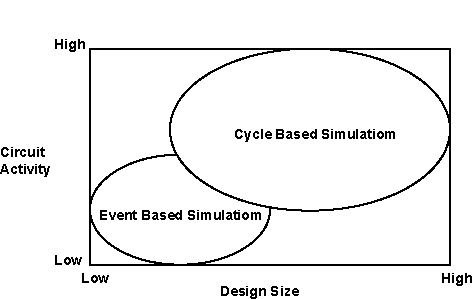
Where two simulations
are appropriate
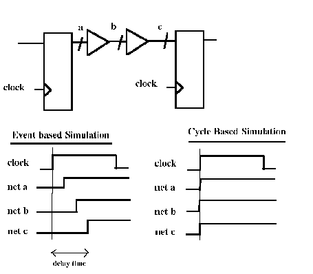
Comparison between
Event Based and Cycle based Simulation
Finite State Machines in Verilog
State machine design is becoming more complex due to increasing time constraints and verification issues. Following papers provide good insight into design and optimization.
1] State Machine Design Techniques for
Verilog and VHDL : by Steve Golson, Trilobyte Systems
PDF
version of article
Text Version : http://www.synopsys.com/news/pubs/JHLD/JHLD-099401
FSMDesigner
It is a Java based Finite State Machine
(FSM) editor, which allows the hardware designer to specify complex control
circuits in an easy and comfortable way. The graphical FSM is converted
into a proprietary state/flow table format. It can be translated into efficient
and synthesizable Verilog HDL.
More Information : http://mufasa.informatik.uni-mannheim.de/lsra/projects/fsmdes/
The Verilog beginners need examples of
simple building blocks to learn coding techniques. This section tries to
create a database of such designs. If you have any such design please mail
to Rajesh Bawankule (rajesh52@hotmail.com)
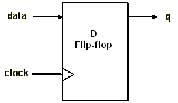
| D
Type Flip-flop:
A sample code is shown below. A header indicates a minimum set of information needed to identify and maintain the code. |
 |
//
// Copyleft (C) 1998 by Rajesh Bawankule
// This model is available for free distribution
//
// file name : dff.v
// last modified : 07/23/98
// function : d flip flop
//
////////////////////////////////////////////////////////////////////
module dff (data, clock, q);
// port list
input data,
clock;
output q;
// reg / wire declaration
for outputs / inouts
reg
q;
// logic begins here
always @(posedge clock)
q <= data;
endmodule
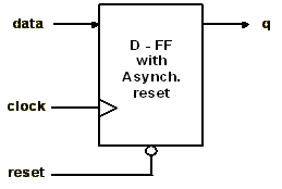
| D
Type Flip-flop with asynchronous reset:
Example of D type Flip flop with asynchronous reset. |
 |
// port list
input data, clock, reset;
output q;
// reg / wire declaration
for outputs / inouts
reg
q;
// reg / wire declaration for internal signals
// logic begins here
always @(posedge clock
or negedge reset)
if(reset == 1'b0)
q <= 1'b0;
else
q <= data;
endmodule
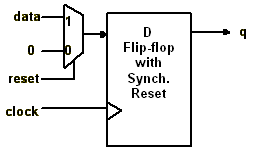
| D
Type Flip-flop with Synchronous reset:
Example of D type Flip flop with synchronous reset. |
 |
// port list
input data, clock, reset;
output q;
// reg / wire declaration
for outputs / inouts
reg
q;
// reg / wire declaration for internal signals
// logic begins here
always @(posedge clock)
if(reset == 1'b0)
q <= 1'b0;
else
q <= data;
endmodule
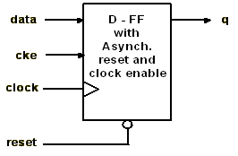
| D Type Flip-flop with asynchronous reset and clock enable |
 |
// port list
input data, clock, reset, cke;
output q;
// reg / wire declaration
for outputs / inouts
reg
q;
// logic begins here
always @(posedge clock
or negedge reset)
if (reset == 0)
q <= 1'b0;
else if (cke == 1'b1)
q <= data;
endmodule
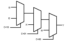
| 4:1 Multiplexer Using case statement |
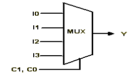 |
input I0,I1,I2,I3,C0,C1;
output Y;
reg Y;
always@(I0 or I1 or I2 or I3 or C0
or C1) begin
case ({C1,C0})
2'b00 : Y = I0 ;
2'b01 : Y = I1 ;
2'b10 : Y = I2 ;
2'b11 : Y = I3 ;
endcase
end
endmodule
| 4:1
Multiplexer Using if-else statements:
This implementation gives priority encoder structure. |
 |
module mux4_1_if(Y,I0,I1,I2,I3,C0,C1);
input I0,I1,I2,I3,C0,C1;
output Y;
reg Y;
always@(I0 or I1 or I2 or I3 or C1)
begin
if ({C1,C0}
== 2'b00) Y = I0;
else if ({C1,C0}
== 2'b01) Y = I1;
else if ({C1,C0}
== 2'b10) Y = I2;
else if ({C1,C0}
== 2'b11) Y = I3;
end
endmodule
4:1
Multiplexer Using assign statements :
This implementation is given to show flexibility
of Verilog language. This type of coding is generally not preferred for
mux implementation as it is difficult to debug.
module mux4_1_assign(Y,I0,I1,I2,I3,C0,C1);
input I0,I1,I2,I3,C0,C1;
output Y;
wire a_0, a_1, a_2, a_3;
// intermediate signals
wire c0_n, c1_n;
wire Y;
assign c0_n = ~C0;
assign c1_n = ~C1;
assign a_0 = I0 & c1_n & c0_n;
assign a_1 = I1 & c1_n & C0;
assign a_2 = I2 & C1 & c0_n;
assign a_3 = I3 & C1 & C0;
assign Y = a_0 | a_1 | a_2 | a_3;
endmodule
Behavioral
FIFO model:
This is a behavioral fifo model, which
enables simultaneous shift-in and shift-out, posedge triggered and
asynch reset,
Assumptions:
- no shift-in is made on a full fifo
- no shift-out is made on an empty fifo
This model is contributed by Lars Rzymianowicz
(lr@mufasa.informatik.uni-mannheim.de)
module fifo(
dout, // head of fifo
full, // no more space, no shift-in allowed
half, // fifo is >=50% full
quarter, // fifo is >=25% full
empty, // head of fifo is invalid data
clk,
res_,
din, // data to store
shiftin, // store data from din in fifo
shiftout); // i've read the head of fifo, show me next
parameter WIDTH = 32; // bit width
parameter DEPTH = 16; // depth of fifo
output [(WIDTH-1):0] dout;
output
full, half, quarter, empty;
reg
full, half, quarter, empty;
input
clk, res_, shiftin, shiftout;
input [(WIDTH-1):0] din;
reg [(WIDTH-1):0] entry [0:(DEPTH-1)];
// the register stages
integer
wp;
// write pointer (points to first free slot)
integer
i; // loop count
// first stage of fifo is output
assign dout = entry[0];
always @(posedge clk or negedge res_) //
trigger new evaluation
begin
if (res_ == 0) // it's
a reset
begin
wp
= 0; // the initial values
full
<= 1'b0;
half
<= 1'b0;
quarter <=
1'b0;
empty
<= 1'b1;
end
else // it's a posedge
of clk
begin
case ({shiftin,
shiftout})
2'b00: ; // nothing to do
2'b01: // shift-out(assumes: at least 1 valid value in fifo)
begin
for (i=1; i<wp; i=i+1) // shift all valid entries
entry[i-1] <= entry[i];
wp = wp-1;
full <= 1'b0;
half <= (wp >= (DEPTH/2)) ? 1'b1 : 1'b0;
quarter <= (wp >= (DEPTH/4)) ? 1'b1 : 1'b0;
empty <= (wp == 0) ? 1'b1 : 1'b0;
end
2'b10: // shift-in (assumes: at least 1 entry free)
begin
entry[wp] <= din;
wp = wp+1;
full <= (wp == DEPTH) ? 1'b1 : 1'b0;
half <= (wp >= (DEPTH/2)) ? 1'b1 : 1'b0;
quarter <= (wp >= (DEPTH/4)) ? 1'b1 : 1'b0;
empty <= 1'b0;
end
2'b11: //simultaneous shift-in and -out
begin // (at least 1 valid entry)
for (i=1; i<wp; i=i+1)
entry[i-1] <= entry[i];
entry[wp-1] <= din;
end
endcase // case ({shiftin, shiftout})
end // else: !if(res_ == 0)
end // always @ (posedge clk or negedge res_)
endmodule
Examples
from "The Verilog Hardware Description Language"
by D.E. Thomas and P.R. Moorby
Micron memory
simulation models with testbenches.
Micron memory models are available for
EDO DRAM, SDRAM, SRAM, SGRAM, SLDRAM with various flavors and testbenches.
http://www.micron.com/products/
Synthesis
Synthesis: It is a process to map and
optimizing higher level HDL description to technology cells (gates, flip
flops etc.)
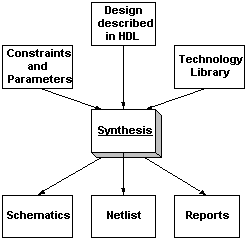
HDL Description: This is description of design in Verilog. One has to use subset of constructs as synthesis tools does not support all of them.
Technology Library: This file contains functional description and other information related to area and speed for all the cells of particular technology.
Here "technology" means information about particular process for particular vendor. For example Company X, Standard Cell, 0.18 micron, Y Process, Z Type.
Constraints: This optional file contains information about physical expectations from design. For example speed and area.
Netlist: A netlist is a text file description of a physical connection of components.
Reports: This optional output file contains physical performance of design in terms of speed and area.
Schematic: Some tools provide the facility to view netlist in terms of schematics for better understanding of design and to match the results with the expectations.
Simple example:
Following trivial example explains the
Synthesis process. In this example only always procedural statement is
used.
module test (out, in1, in2); // behavioral description
input in1, in2;
output out;
reg out;
reg temp;
// temporary register
always@(in1 or in2) begin
temp = ~in2;
out = ~in1 ^ temp; // I am trying to have
exor with inverted
end
// inputs
endmodule
---------------
after synthesis one gets following "netlist"
in verilog. Note that XOR2 is module picked up from technology library.
It will be different for different libraries.
---------------
module add ( out , in1 , in2 ); // netlist
output out ;
input in1 ;
input in2 ;
XOR2 instance_name (.Y (out ),.A (in1 ),.B (in2 ) );
endmodule
--------------
Note that synthesis tool optimized the
logic. Netlist can be obtained in other formats like .EDIF, .vhdl.
Here is an example of .xnf format ( Xilinx netlist format)
--------------
LCANET, 5
USER, LIBRARY_NAME, temp
USER, CELL_NAME, test
USER, VIEW_NAME, INTERFACE
SIG, out, S
SIG, in1, S
SIG, in2, S
SYM, instance_name, XOR2
PIN, A, I, in1,
PIN, B, I, in2,
PIN, Y, O, out, 1.000000
END
EOF
---------
You can get detailed information on netlist
formats in respective synthesis tool manuals / guides and SDF manual.
Now try the same example which uses always, assign and simple gate level description. You will find that results are identical. Synthesis tool optimizes the description and produces the minimal hardware required.
module xor_example (in1, in2, out);
input in1, in2;
output out;
reg out;
reg temp1;
wire temp2;
always @(in1 or in2) begin
temp1 = in1 &
~in2;
end
assign temp2 = ~in1 & in2;
or my_or (out, temp1, temp2);
endmodule
Unsupported Verilog Language Constructs
Synthesis tools are not so intelligent.
They try to infer hardware from HDL description. Most synthesis tools does
not support the following Verilog constructs:
?Unsupported definitions and declarations
- primitive definition
- time declaration
- event declaration
- triand, trior, tri1, tri0, andtriregnet
types
- Ranges and arrays for integers
?Unsupported statements
- defparam statement
- initial statement
- repeat statement
- delay control
- event control
- wait statement
- fork-join statements
- deassign statement
- force statement
- release statement
- Assignment statement with a variable
used as a bit-select on the left side of the equal sign
?Unsupported operators
- Case equality and inequality operators
(=== and !==)
- Division and modulus operators for variables
?Unsupported gate-level constructs
- nmos, pmos, cmos, rnmos, rpmos, rcmos, pullup, pulldown,
tranif0, tranif1, rtran, rtrainf0, andrtrainf1gate
types
?Unsupported miscellaneous constructs
- Hierarchical names within a module
Currently there is no single free synthesis tool available. Following is a list of commercially available sythesis tools.
- Synopsys, Inc.
- Design Compiler and Behavioral Compiler
- Synplicity, Inc.
- Synplify
- Exemplar Logic
- Leonardo Spectrum
- Mentor Graphics Corp.
- AutoLogic and PLDSynthesis
- Avanti
- Asyn
- Cadence Design Systems Inc.
- Ambit
- Magma Design Automation
-
Blast Create
There is Verilog Synthesis Subset Working Group (IEEE PAR 1364.1) working on formalizing Verilog subset used in Synthesis.
http://www.eda.org/vlog-synth/
IEEE P1364.1/D1.4 Draft Standard for Verilog
Register Transfer Level Synthesis is available at
http://www.eda.org/vlog-synth/vlogrtl.pdf
"RTL Coding Styles That Yield Simulation
and Synthesis Mismatches" by Don Mills is available in pdf format
at http://www.eda.org/vlog-synth/Mills_Final.pdf
 |
Logic Synthesis
Using Synopsis
by Pran Kurup, Taher Abbasi Price: $120.00 Hardcover 2nd edition (June 1997) Kluwer Academic Pub; ISBN: 079239786X |
 |
Behavioral Synthesis
: Digital System Design Using the Synopsis Behavioral Compiler
by David W. Knapp Price: $68.00 Hardcover - 231 pages Bk&Disk edition (June 1996) Prentice Hall; ISBN: 0135692520 |
 |
Advanced Asic
Chip Synthesis : Using Synopsys Design Compiler and Primetime
by Himanshu Bhatnagar Hardcover (June 1999) Kluwer Academic Pub; Price: $115.00 ISBN: 0792385373 |
Usenet
group related to synthesis
- John Cooley maintains moderated email based ESNUG (Synopsys User Group) email list. Past and present email archives can be found at http://www.DeepChip.com/
- Usenet group comp.cad.synthesis is created to discuss synthesis related questions. One get postings through http://www.deja.com/ and other sites.
This section lists questions asked in comp.lang.verilog usenet forum and their answers. This section is kept on separate page here.