 VHDL
essentials
VHDL
essentialsVHDL
essentials
prepared by P. Bakowski
Contents: description domains and levels, design cube, describing structure, describing behaviour, discrete event time model, signal representation, design entities, first example , second example, compilation and elaboration
![]() Descriptional
aspects and abstraction levels
Descriptional
aspects and abstraction levels
The hardware may be designed and described along several aspects or domains:
Then the domains may be presented at different abstraction levels, such as:
At these different abstraction levels the time may be perceived as:
The information may be treated:
Among the models best suited to express the decriptional capacities of VHDL is the Design Cube Model presented by W. Ecker and M.Hofmeister [Euro-VHDL'92]
The design cube model is built on three dimensional design space involving :
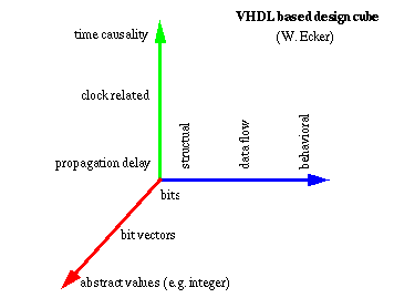
Design space cube (W. Ecker)
Using the "design cube" 27 of different levels of temporal and functional abstraction may be identified. Only few of them have well established meaning.
Abstract or algorithmic models are built from: behavioral specification, time causality, and abstract values.
Register Transfer models are build upon data flows, clock related synchronization, and composite bit values.
Finally logic level models are mainly structural, with propagation delays, and bit values.
A digital electronic system can be described as a module with inputs and/or outputs. The electrical values on the outputs are some function of the values on the inputs.
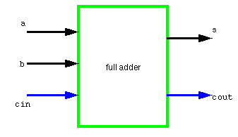
VHDL module called entity
The above module has tree inputs, a, b and cin , and two outputs s and cout. Using VHDL terminology, we call the module full adder a design entity , and the inputs and outputs are called ports .
One way of describing the function of a module is to describe how it is composed of sub-modules.
Each of the sub-modules is an instance of some entity, and the ports of the instances are connected using signals .
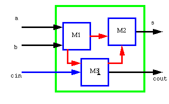
Hierarchically connected entities called components
Structural description of full adder might be composed of instances of entities M1, M2 and M3. This kind of description is called a structural description. Note that each of the entities M1, M2 and M3 might also have a structural description.
In many cases, it is not appropriate to describe a module structurally. One such case is a module which is at the bottom of the hierarchy of some other structural description.
For example, if you are designing a system using IC packages bought from an IC shop, you do not need to model the internal structure of an IC. In such cases, a description of the function performed (behavior) by the module is required, without reference to its actual internal structure.
Such a description is called a functional or behavioral description. To illustrate this, suppose that the function of the entity full adder in the figure above could be the full adder functions:
s = a xor b xor cin;
cout = (a and b) or (a and cin) or (b and cin);
More complex behaviours cannot be described purely as a function of inputs. In systems with feedback, the outputs are also a function of time.
VHDL solves this problem by allowing description of behaviour in the form of a simulatable model.
Once the structure and behaviour of a module have been specified, it is possible to simulate the module by executing its bevioural description. This is done by simulating the passage of time in discrete steps (events). At some simulation time, a module input may be stimulated by changing the value on an input port. The module reacts by running the code of its behavioural description and scheduling new values to be placed on the signals connected to its output ports at some later simulated time. This is called scheduling a transaction on that signal. If the new value is different from the previous value on the signal, an event occurs, and other modules with input ports connected to the signal may be activated.
The simulation starts with an initialisation phase, and then proceeds by repeating a two- stage simulation cycle .
In the initialisation phase, all signals are given initial values, the simulation time is set to zero, and each module's behaviour program is executed. This usually results in transactions being scheduled on output signals for some later time. In the first stage of a simulation cycle, the simulated time is advanced to the earliest time at which a transaction has been scheduled. All transactions scheduled for that time are executed, and this may cause events to occur on some signals.
In the second stage, all modules which react to events occurring in the first stage have their behaviour program executed. These programs will usually schedule further transactions on their output signals. When all of the behaviour programs have finished executing, the simulation cycle repeats. If there are no more scheduled transactions, the whole simulation is completed.
The purpose of the simulation is to gather information about the changes in system state over time. This can be done by running the simulation under the control of a simulation monitor . The monitor allows signals and other state information to be viewed or stored in a trace file for later analysis. It may also allow interactive stepping of the simulation process, much like an interactive program debugger.
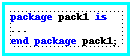
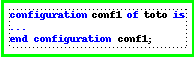
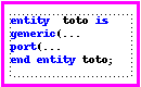
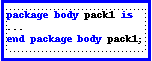
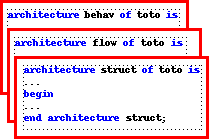
The figure below shows five kinds of VHDL design units. The primary design units are entity, package and configuration. The secondary design units are architecture(s) and package body declaration.
![]() Primary design units -
click on them
Primary design units -
click on them
![]() Secondary design units
Secondary design units
In the following example only two kinds of design units are used: entity and architecture. Packages are useful for the bigger designs where some number of data types, functions and procedures must be defined before the designing of the system built from several entities and architectures.
Configuration module is required if you construct a complex system assembled from several components (entities). It allows to select the required components from the specified library. (e.g. IEEE library)
![]() Your
first example : combinational circuit
Your
first example : combinational circuit
In this section we will look at a small example of a VHDL description of a full adder to give you a feel for the language and how it is used. We start the description of an entity by specifying its external interface, which includes a description of its ports. The adder might be defined as:
This specifies the entity with 3 inputs and 2 outputs, all of which are bit values, that is, they can take on the only two values: `0' and `1'.
The folowing architecture is described functionally with two concurrent signal assignments.
-- description of adder using concurrent signal assignments
architecture rtl of adder is
begin
end rtl;
It may be developed in order to introduce timing information through the generic statement which contains the predefined temporal parameters - delays:
-- single-bit adder
entity adder is
end adder;
Which provides us with a reformulated architecture:
-- description of adder using concurrent signal assignments
architecture rtl of adder is
begin
sum <= (a xor b) xor cin after sum_del;
cout <= (a and b) or (cin and a) or (cin and b) after carry_del;
end rtl;
![]() Signal
representation and its implementation
Signal
representation and its implementation
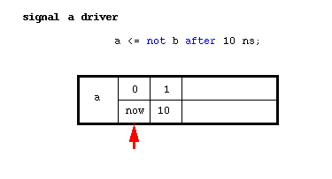
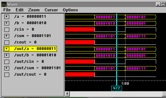
The above waveform shows the functionning of the given example (simulator) The same circuit can be described structurally using predefined gate components.
![]() Structural
architecture of adder description
Structural
architecture of adder description
The following architecture uses bgates library containing the description of gates like xorg, andg, and org.
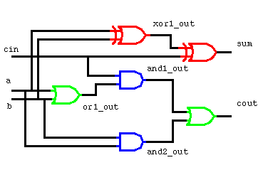
These components are directly instantiated and interconnected through port map clause.
Note that the same component may be instantiated several times under different instantiation names.
The direct instantiation may be used only for the components/entities with single architecture.
To chose the components having more than one architecture one must use configuration clause.
-- description of adder using component direct instantiation statements
use work.bgates.all;
architecture structural of adder is
signal xor1_out, and1_out, and2_out, or1_out : bit;
begin
xor1: xorg port map(in1 => a,in2 => b, out1 => xor1_out);
xor2: xorg port map(in1 => xor1_out, in2 => cin,out1 => sum);
and1: andg port map(in1 => a,in2 => b,out1 => and1_out);
or1: org port map(in1 => a,in2 => b,out1 => or1_out);
and2: andg port map( in1 => cin, in2 => or1_out, out1 => and2_out);
or2: org port map(in1 => and1_out,in2 => and2_out, out1 => cout);
end structural;
![]() Waveform from the simulator
Waveform from the simulator
![]() Your
second example : sequential circuit
Your
second example : sequential circuit
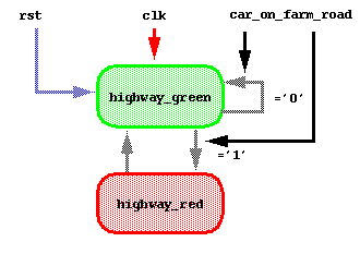
Trafic light controller is a classic example of a simple state machine. The traffic light is place at the intersection of a busy highway and a farm road. The light should always allow cars on the highway to travel through the intersection, unless a car appears on the subordinated farm road. The car on the farm road should be allowed to cross; then the light may should return to state which allows the highway traffic.
The following state diagram represents the states and transitions to be performed by the sequencer. The sequencer is initialized to the state highway_green. When a car on the farmroad appears (car_on_farm_road input signal), the sequnces transits to highway_red state. If there is no (more) car on the farm road the sequncer is set back to the highway_green state. There are two main signals activating the sequencer:
The VHDL description of sequencer uses standard logic (IEEE.std_logic_1164) defined for synthetizable models.
The internal state is an enumerated type highway_light_state composed from two states highway_green and highway_red.
library IEEE;
use IEEE.std_logic_1164.all;
entity light_controller is
port(clk,rst,car_on_farm_road: in std_ulogic; highway_light: out std_ulogic);
end light_controller;
architecture synthesis_able of light_controller is -- this architecture is synthesisable
type highway_light_state is ( highway_green ,highway_red);
signal next_state: highway_light_state;
begin
main_p: process(clk,rst)
begin
if rst='1' then
next_state <= highway_green;highway_light,= '1';
elsif clk'event and clk='1' then -- detection of rising edge
case next_state is
when highway_green=>
highway_light<= '1';
if car_on_farm_road = '1' then
next_state <= highway_red;
else
next_state <= highway_green;
end if;
when highway_red=>
highway_light<= '0';
next_state <= highway_green;
end case;
end if;
end process main_p;
end synthesis_able;
![]() Compilation,
elaboration and simulation
Compilation,
elaboration and simulation
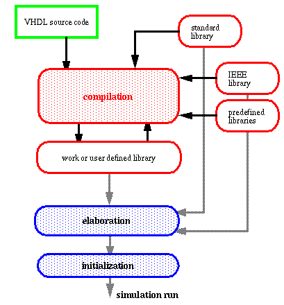
The simulation process of VHDL entities requires two preliminary steps:
The compilation consists in the analysis of the source description and the generation of an intermediary code stored in the design library.
There are several kinds of design libraries:
The next step is elaboration which performs several actions such as:
The simulation process starts with several initializing actions such as:
The following figure shows different elements and actions required before the simulation process can start.